

B. Optics with Nanostructures
-
Near-Field Spectroscopy of Single Quantum Dots
Florian Bickel and Khaled Karraï. -
Reflected Image of a Strongly Focused Spot
Lukas Novotny, Robert D. Grober, and Khaled Karraï. -
Magneto Optical Spectroscopy on Single Quantum Rings
Christian Schulhauser, Dirk Haft, Khaled Karraï, and Richard J. Warburton. -
Luminescence Quenching in InAs Quantum Dots
Dirk Haft, Richard J. Warburton, and Khaled Karraï.
Near-Field Spectroscopy of Single Quantum Dots
Florian Bickel and Khaled Karraï,
in cooperation with Gilberto Medeiros-Ribeiro, Jorge M. Garcia,
Winston Schoenfeld, and Pierre M. Petroff.
Quantum dots are nanometer-sized clusters that confine electrons in all three directions. They can be fabricated in a semiconductor system by embedding islands of low-bandgap material in a higher bandgap material, i.e. InAs in GaAs. As a consequence these artificial atoms show sharp optical transitions in the infrared which can be investigated to get information about the shell structure caused by the three dimensional confinement. Unfortunately statistical fluctuations of the dot size prevent the observation of sharp lines in the spectra of dot ensembles. Using near-field scanning techniques, however, it is possible to address single dots for illumination. In our experiments a wavelength tuneable laser is resonantly exiting one of these quantum objects while a gate structure in which the dots are embedded is controlling the global electron filling of the dots. Thus it is possible to study the many body absorption answer as well as the intrinsic line widths of differently charged quantum states.
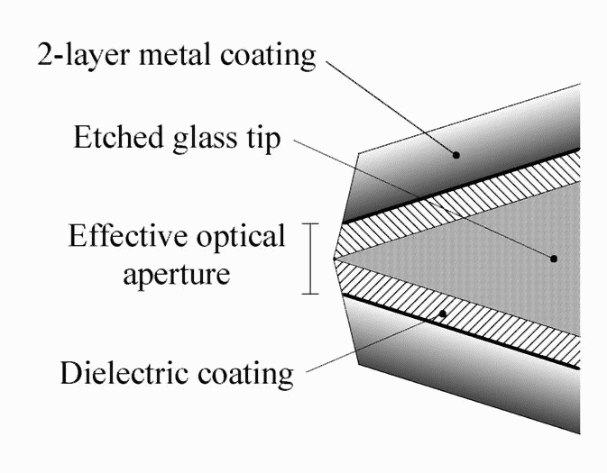
It is essential for these low-intensity experiments to provide enough laser power at the point of examination. Hence we use etched fibre tips for our near-field setup as they have much better transmission coefficients then pulled ones. Normally the aperture size and therefore the transmission of these tips cannot be controlled but is set by the quality of the fabrication process. We invented a technique for making tips with a desired opening so that this important feature can be tailored to the experiment.
Reflected Image of a Strongly Focused Spot
Lukas Novotny
The Institute of Optics, University of Rochester,
Rochester, New York 14627
Robert D. Grober
Department of Applied Physics, Yale University, New
Haven, Connecticut 06520
Khaled Karraï
We describe the reflection of a strongly focused beam from an interface between two dielectric media. If the beam is incident from the optically denser medium, the image generated by the reflected light is strongly aberrated. This situation is encountered in high-resolution confocal microscopy and data sampling based on solid immersion lenses and oil immersion objectives. The origin of the observed aberrations lies in the nature of total internal reflection, for which there is a phase shift between incident and reflected waves. This phase shift displaces the apparent reflection point beyond the interface, similarly to the Goos-Hänchen shift.
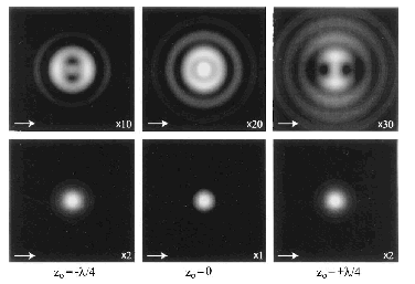
Figure 1. Reflected images of a diffraction-limited focused spot. The spot is moved in steps of a quarter wave length across the interface. zo is positive (negative) when the focus is below (above) the interface. Upper row, glass-air interface , lower row, glass-metal interface. The arrow indicates the direction of polarization of the incoming beam. Image size, 4.75 x wavelength.
- L. Novotny, R. D. Grober, and K. Karraï, "Reflected Image of a Strongly Focused Spot", Opt. Lett. 26, 789-791 (2001).
Magneto Optical Spectroscopy on Single Quantum Rings
Christian Schulhauser, Dirk Haft, Khaled Karraï, and Richard
J. Warburton,
in cooperation with Gilberto Medeiros-Ribeiro, Jorge M. Garcia,
Winston Schoenfeld, and Pierre M. Petroff.
We investigated the excitonic behaviour of Quantum Rings (QR) within an electric and a magnetic field. All measurement were done by the use of a low temperature confocal microscope where the emitted photoluminescence was analysed by a spectrometer. From the electro optical properties we find a Stark Shift Effect from which we could derive a permanent dipole momentum in a range of p=-0.2nme to p=-2.5nme. According to the sign convention of the dipole momentum related to the field effect structure, we could find an electron position above the hole position.
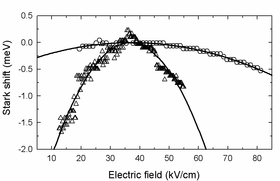
Figure 2. The electric field dependent Photoluminescence of two different QR.
The magnetic field experiments on QRs resulted in an observation for the Zeeman Effect and a diamagnetic shift. By doing statistics on many QRs we find three different types of Rings determined by the diamagnetic properties. First the diamagnetic shift is dependent on the number of electrons confined in the QR potential, second the diamagnetic shift is independent of the charging effect and third the diamagnetic shift shows a "kink" in its dispersion which comes from the penetration of a flux quantum through the QR.
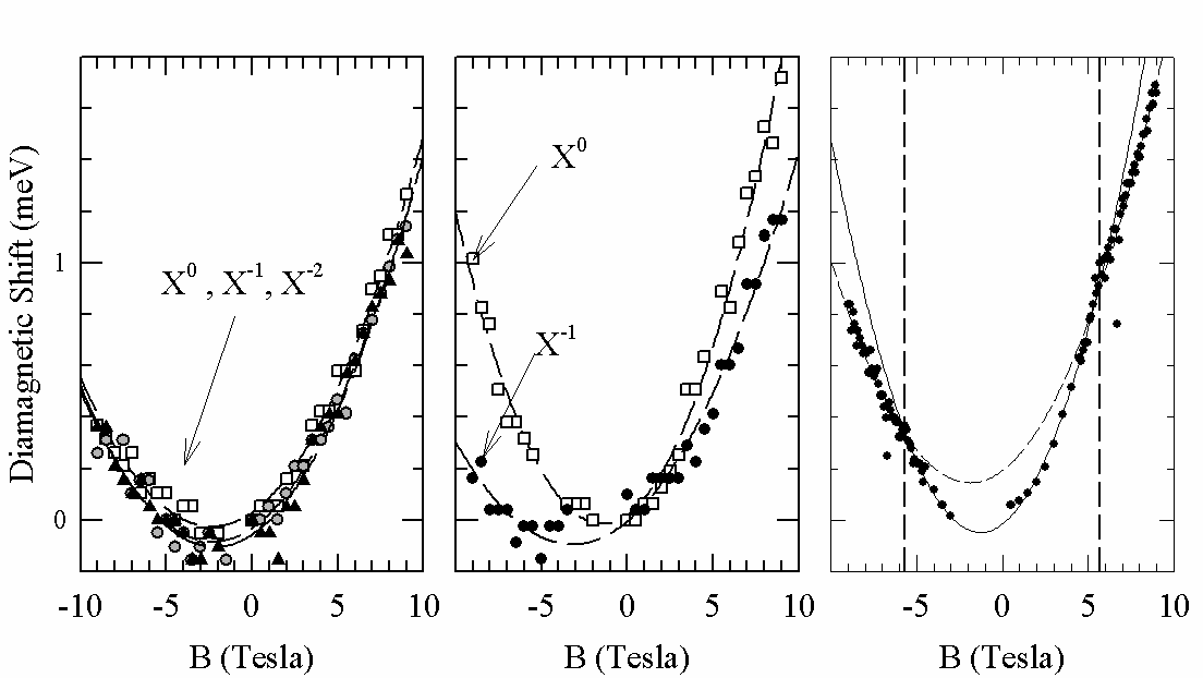
Figure 3. Categorization for the three different types of QRs. From left to right it shows the charge independent, the charge dependent and the "kink" like behaviour of QRs in a magnetic field.
Luminescence Quenching in InAs Quantum Dots
Dirk Haft, Richard J. Warburton, and Khaled Karraï,
in cooperation with Serge Huant,
and Gilberto Medeiros-Ribeiro, Jorge M. Garcia,
Winston Schoenfeld, and Pierre M. Petroff.
We report how photoluminescence from self-assembled InAs quantum dots depend on pumping power and vertical electric field. The InAs dots, which are embedded in a capacitor-like structure, act as efficient trapping centers for excitons. At a high enough electric field, however, the photoexcited electrons tunnel out of the dots fast enough to quench the emission. For samples with two adjacent layers of vertically aligned dots, we find that the threshold voltage for quenching depends very strongly on the optical pumping power. In total contrast to this, we find no comparable effect for samples grown with a single layer of dots. We explain this in terms of efficient storage of electrons and holes in the double-layer samples.

Figure 4. Inset: energy diagram of
a double-layer dot sample b1 =25 nm,
b2 =45 nm, and d =175 nm.
The differential
capacitance a), and integrated PL emission b) as a function
of the gate voltage U. The threshold voltage of the PL
quenching is shown c) as a function of the illumination
power (proportional to the PL emission).
- D. Haft, et al., "Luminescence Quenching in InAs Quantum Dots", Appl. Phys. Lett. 78, 2946-2948 (2001).